
Logic NAND Gate
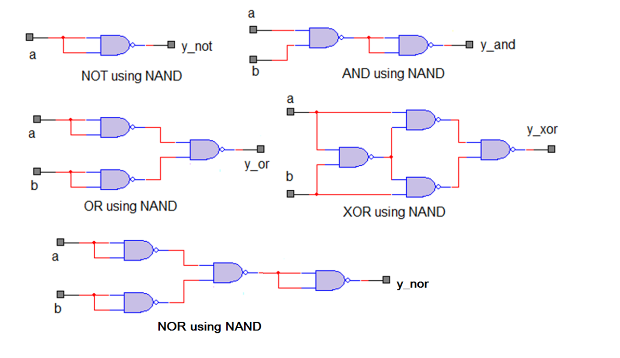
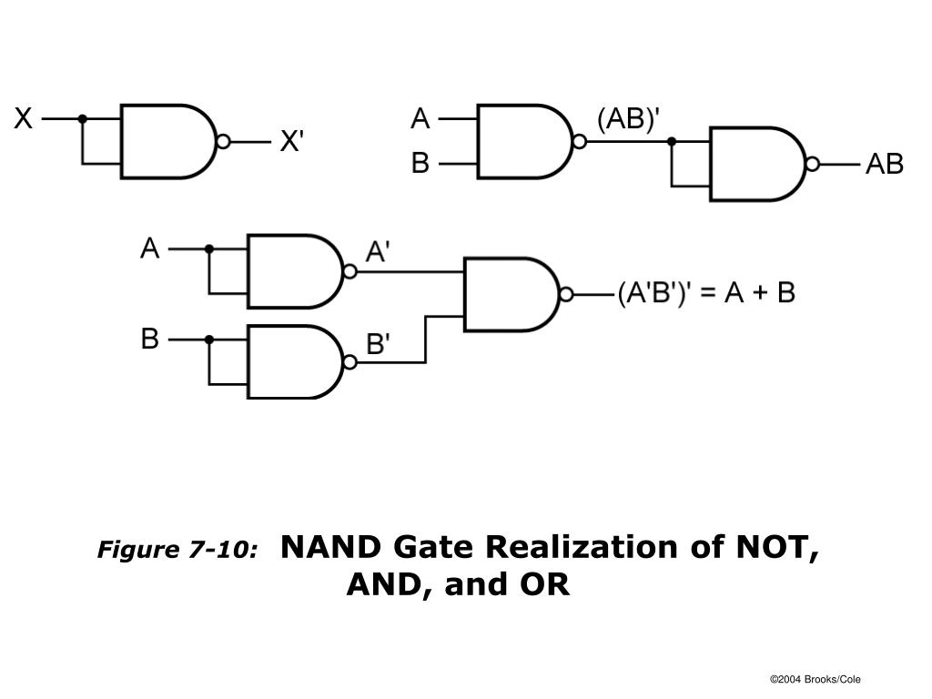
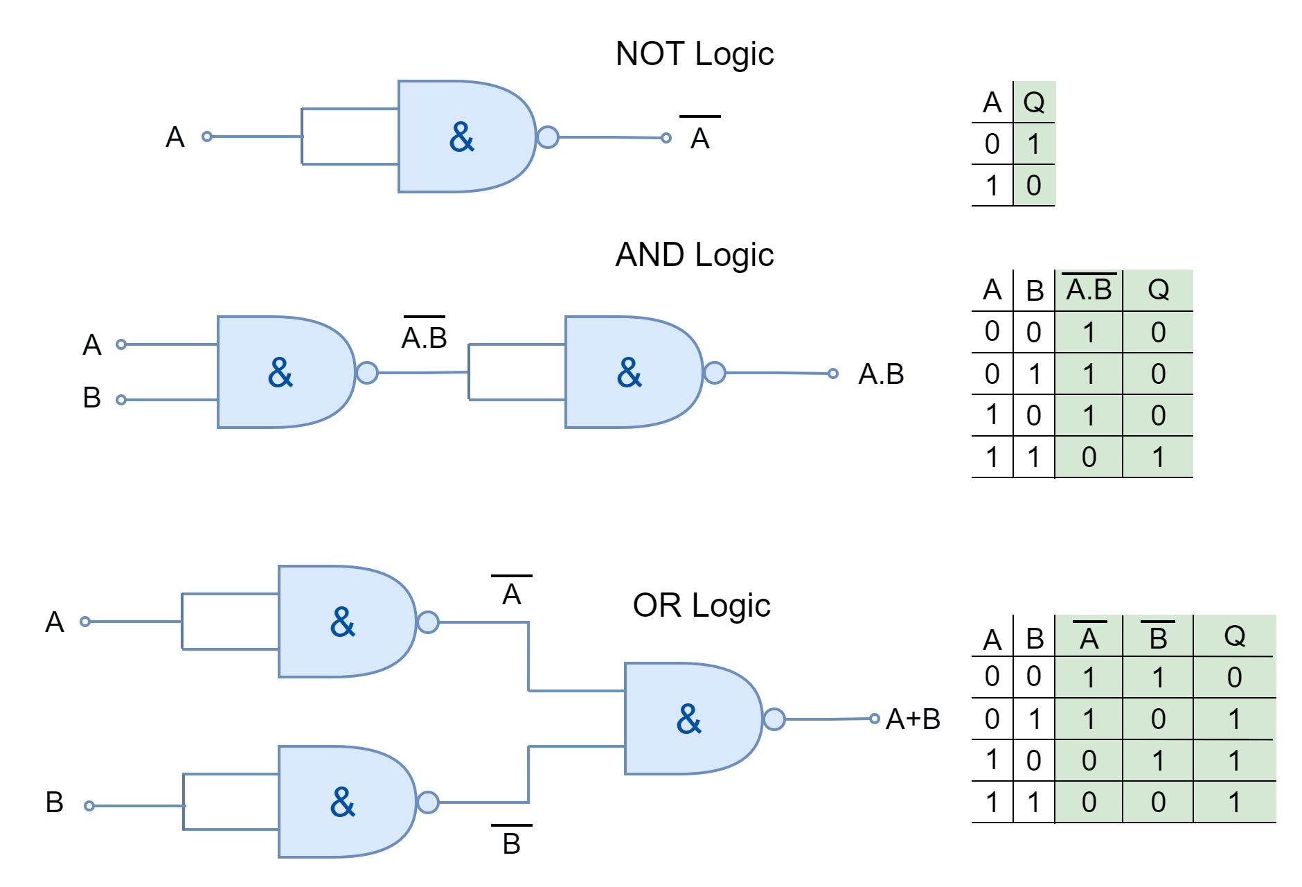
Implementation of OR Gate from NAND Gate. To realize the OR gate from NAND gate, we first complement the inputs A and B. This is done by the NAND Gate in the above Figure. Then, these complemented inputs, i.e. A' and B' are applied to a NAND Gate. Thus, we get, Y= () = A+B.

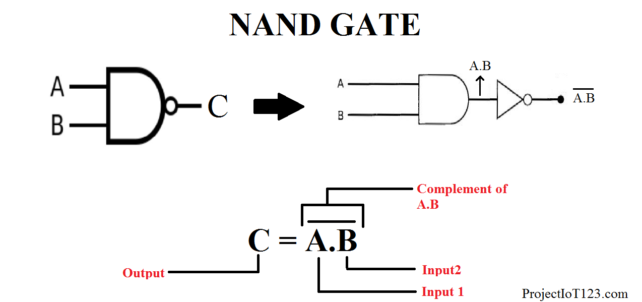
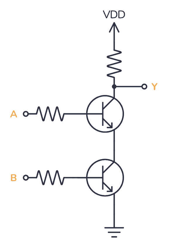
Circuit Diagram For Nand Gate
The implementation of an AND gate using NAND gate is shown in Figure-3. From this circuit diagram, it is clear that the implementation of the AND gate from NAND gate is quite simple, as we just require two NAND gates. Where, the first NAND gate produce a complement binary product of inputs A and B, while the second NAND gate again complement.
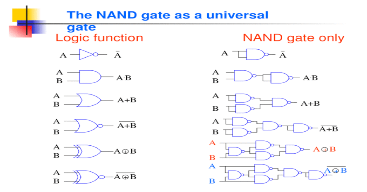
The NAND gate as a universal gate Logic function NAND gate only AA A B A.BA.B A B A+B A B A B A
The NAND-based derivation of the NOT gate is shown in Figure 1. Also, it is important to note that the inputs of the NAND gates are connected together; the same input. In Figure 2 & 3, the NAND-based configuration was derived, the two possible inputs, zero and one, were tested, and the results were observed.
Nand Logic Gate Circuit Diagram
What is an AND Gate? AND gate is the fundamental logic gate that executes the logical multiplication of binary input. The AND operation is carried out in the same way as standard multiplications of 1s and 0s. An AND gate is a logic circuit that performs AND operations on the input of the circuit.
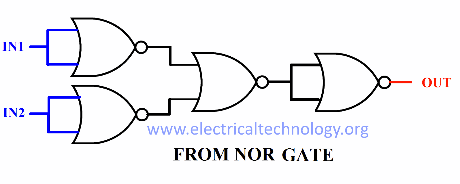
Digital Logic NAND Gate Universal Gate Electrical Technology
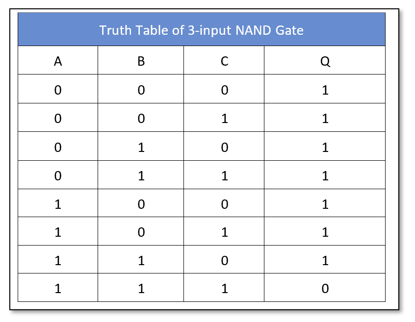
Three-Input NAND Gate. As the name suggests, it has three inputs and only one output. There are 2 3 = 8 combinations of input and output. Symbol of AND Gate. Given Below is the Symbol of NAND gate, A and B represent the two inputs. The NAND gate performs the logical NAND operation on the inputs. The output is represented by the line extending.
Nand Gate Circuit Diagram Using Diode
NAND gate. In digital electronics, a NAND gate ( NOT-AND) is a logic gate which produces an output which is false only if all its inputs are true; thus its output is complement to that of an AND gate. A LOW (0) output results only if all the inputs to the gate are HIGH (1); if any input is LOW (0), a HIGH (1) output results.

Schottky TTL NAND GATE and Comparison with Basic TTL Gate YouTube
The NAND gate expresses an AND gate and is followed by an inverter. It consists of 2 or more input signals. This provides 0 output only when the input is 1. It provides 1 output when the input is 0. The British mathematician De Mergen's second theory says that the NAND gate is similar to a negative (bubbling) OR gate.

NAND gate as Universal Gate YouTube
The NAND gate or "NotAND" gate is the combination of two basic logic gates, the AND gate and the NOT gate connected in series. The NAND gate and NOR gate can be called the universal gates since the combination of these gates can be used to accomplish any of the basic operations. Hence, NAND gate and NOR gate combination can produce an.

Circuit Diagram For Nand Gate
TTL NAND and AND gates. Suppose we altered our basic open-collector inverter circuit, adding a second input terminal just like the first: This schematic illustrates a real circuit, but it isn't called a "two-input inverter.". Through analysis, we will discover what this Circuit's logic function is and correspondingly what it should be.
VHDL Tutorial 7 NAND gate as universal gate using VHDL
NAND Gate. The output is high when either of inputs A or B is high, or if neither is high. In other words, it is normally high, going low only if both A and B are high. The NAND gate and the NOR gate can be said to be universal gates since combinations of them can be used to accomplish any of the basic operations and can thus produce an.

Nand Gate Diagram
If you want to experiment and build circuits with NAND gates, you'll find them in both the 4000 IC series and the 7400 IC series:. 4011: Four 2-input NAND gates; 4023: Three 3-input NAND gates; 4093: Four 2-input NAND gates (Schmitt trigger inputs); 4572: One NAND gate (plus a few other gates); 40107: Two 2-input NAND gates; 74HC00: Four 2-input NAND gates (HC is the family, can also be LS.
PPT FIGURES FOR CHAPTER 7 MULTILEVEL GATE CIRCUITS NAND AND NOR GATES PowerPoint Presentation
As in each of the first three cases, a full AND (which would be true and true) isn't present. Hence, the outcome is true ( 1 ). For the last input, true and true, a full AND is present and thus (due to the NOT component, the N in NAND ), the outcome is false. In this image, we see an SN7400N chip that has four logic gates, namely, NAND gates.
PPT SLIDES FOR CHAPTER 7 MULTILEVEL GATE CIRCUITS NAND AND NOR GATES PowerPoint Presentation
A two-input NAND gate is a fundamental digital logic gate that produces an output only when either or both inputs are low. In simpler terms, it gives a high output (1) unless both inputs are high (1), in which case, it gives a low output (0). This characteristic makes the NAND gate very flexible and widely used in various electronic applications.
Logic NAND Function
The NAND (Negated AND) gate operates as an AND gate followed by a NOT gate. It acts in the manner of the logical operation "and" followed by negation. The output is false if both inputs are true. Otherwise, the output is true. Another way to visualize it is that a NAND gate inverts the output of an AND gate.
NAND Gate Logic Gates Tutorial
The NAND gate is the most important logic gate in digital electronics. It is one of the universal logic gates.Because other logical gates can be designed by using NAND gates only. This gate is available in IC form. IC7400 is a popular IC that consists of 4 NAND gates.

Implement NAND gate using 21MUX how to implement NAND gate using multiplexer design nand
A NAND gate ("not AND gate") is a logic gate that produces a low output (0) only if all its inputs are true, and high output (1) otherwise. Hence the NAND gate is the inverse of an AND gate, and its circuit is produced by connecting an AND gate to a NOT gate. Just like an AND gate, a NAND gate may have any number of input probes but only.
- 40 Paradise Road Slacks Creek
- Berry Red Hot Summer Tour
- Kings Roof Top Tent Replacement Parts
- Accommodation East Victoria Park Wa
- Us Cities Beginning With B
- Quotes From The Rocky Horror Picture Show
- No Control One Direction Lyrics
- Sd Gundam Battle Alliance Review
- The Newsreader Cast Season 2
- Pubs On North Terrace Adelaide